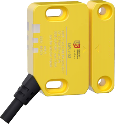
 | ·Miniaturized design,(compatible with 30mm aluminum frames) for easy installation. ·Adopts redundant internal circuits(dual CPU mutual inspection)and self-diagnostic function. ·Intelligent diagnosis and status display:Integrated LED indicators,provide real-time feedback on door switch status and fault information, facilitating quick troubleshooting. ·Support series connection of multiple switches(up to 30 switches can be connected),adapting to complex equipment layouts. ·The actuator coding function has low-level and high-level settings. It performs self-learning to match the sensor during initial installation. The high level function is unique and non-interchangeable. ·Equipped with magnetic latching function,with a magnetic holding force of up-to 15N,which can replace door magnets. |
| Selection catagory |
Configuration type | Coding type | Output mode | Lead wire mode | Direct outlet Cable length | Model |
Basic function | Universal coding | NPN | Direct outlet | 3M | LMC3-52-J2-N-Z3 |
5M | LMC3-52-J2-N-Z5 | ||||
10M | LMC3-52-J2-N-Z10 | ||||
M12 Connector | / | LMC3-52-J2-N-M12 | |||
PNP | Direct outlet | 3M | LMC3-52-J2-P-Z3 | ||
5M | LMC3-52-J2-P-Z5 | ||||
10M | LMC3-52-J2-P-Z10 | ||||
M12 Connector | / | LMC3-52-J2-P-M12 | |||
Unique coding | NPN | Direct outlet | 3M | LMC3-52-J1-N-Z3 | |
5M | LMC3-52-J1-N-Z5 | ||||
10M | LMC3-52-J1-N-Z10 | ||||
M12 Connector | / | LMC3-52-J1-N-M12 | |||
PNP | Direct outlet | 3M | LMC3-52-J1-P-Z3 | ||
5M | LMC3-52-J1-P-Z5 | ||||
10M | LMC3-52-J1-P-Z10 | ||||
M12 Connector | / | LMC3-52-J1-P-M12 | |||
Standard | Universal coding | NPN | Direct outlet | 3M | LMC3-52-B2-N-Z3 |
5M | LMC3-52-B2-N-Z5 | ||||
10M | LMC3-52-B2-N-Z10 | ||||
M12 Connector | / | LMC3-52-B2-N-M12 | |||
PNP | Direct outlet | 3M | LMC3-52-B2-P-Z3 | ||
5M | LMC3-52-B2-P-Z5 | ||||
10M | LMC3-52-B2-P-Z10 | ||||
M12 Connector | / | LMC3-52-B2-P-M12 | |||
Unique coding | NPN | Direct outlet | 3M | LMC3-52-B1-N-Z3 | |
5M | LMC3-52-B1-N-Z5 | ||||
10M | LMC3-52-B1-N-Z10 | ||||
M12 Connector | / | LMC3-52-B1-N-M12 | |||
PNP | Direct outlet | 3M | LMC3-52-B1-P-Z3 | ||
5M | LMC3-52-B1-P-Z5 | ||||
10M | LMC3-52-B1-P-Z10 | ||||
M12 Connector | / | LMC3-52-B1-P-M12 | |||
High-function typle | Universal coding | NPN | Direct outlet | 3M | LMC3-52-G2-N-Z3 |
5M | LMC3-52-G2-N-Z5 | ||||
10M | LMC3-52-G2-N-Z10 | ||||
M12 Connector | / | LMC3-52-G2-N-M12 | |||
PNP | Direct outlet | 3M | LMC3-52-G2-P-Z3 | ||
5M | LMC3-52-G2-P-Z5 | ||||
10M | LMC3-52-G2-P-Z10 | ||||
M12 Connector | / | LMC3-52-G2-P-M12 | |||
Unique coding | NPN | Direct outlet | 3M | LMC3-52-G1-N-Z3 | |
5M | LMC3-52-G1-N-Z5 | ||||
10M | LMC3-52-G1-N-Z10 | ||||
M12 Connector | / | LMC3-52-G1-N-M12 | |||
PNP | Direct outlet | 3M | LMC3-52-G1-P-Z3 | ||
5M | LMC3-52-G1-P-Z5 | ||||
10M | LMC3-52-G1-P-Z10 | ||||
M12 Connector | / | LMC3-52-G1-P-M12 |
 Model description

 M12 Connection cable selection
M12 connection cable |
| Basic function cable(5-pin, 5-core) | LMC3-52--XL-P55C3 |
LMC3-52-XL-P55C5 | |||
LMC3-52-XL-P55C10 | |||
Standard-type cable(8-pin,8-core) | LMC3-52-XL-P88C3 | ||
LMC3-52-XL-P88C5 | |||
LMC3-52-XL-P88C10 | |||
High-function type cable(12-pin,10-core) | LMC3-52-XL-P1210C3 | ||
LMC3-52-XL-P1210C5 | |||
LMC3-52-XL-P1210C10 |
 Indicator light description

Indicator light name | Light color | Status | Status description | Status of OSSD | Detection status of the actuator |
Large indicator light | Green | Light up | In normal operation | ON | Detection status |
Green | Flashing (high- speed) | Switching coding level from low to high, or teaching the matcher | OFF | Detected matcher is incorrect | |
Green | Flashing | Switching coding level from low to high, or teaching the matcher | OFF | Detected matcher is incorrect。 | |
Red and green alternating | Flashing (high- speed) | An untaught actuator is detected when operating at "high" coding level | OFF | Detected matcher is incorrect。 | |
Error during coding level switching | Not fixed | ||||
Red | Light up | Door is in open state. | OFF | Non-detection status | |
Flashing (high- speed) | Error state.The sensor detects an abnormality | OFF | Not fixed | ||
Turn off | — | Power OFF | OFF | Not fixed | |
OSSD indictor light | Green | Light up | OSSD is on | ON | Detection status |
Flashing | OSSD is on,but the door is in an unstable state such as half-open | ON | Detection status | ||
Red | Light up | OSSD is off | OFF | Not fixed | |
Input indicator light | Green | Light up | Safety input is on | Not fixed | Detection status |
Flashing | Self- holding release waiting state(waiting for reset input) | OFF | Not fixed | ||
Turn off | — | Safety input is OFF,or other states. | OFF | Detection status |
 Technical parameter
Model | LMC3-52-J | LMC3-52-B | LMC3-52-G | ||
Type | Basic function type | Standard type | High-function type | ||
Detection distance | Front side | sao(OFF→ON) | 10mm | ||
sar(ON→OFF | 18mm | ||||
Side face | sao(OFF→ON) | 6mm | |||
sar(ON→OFF | 14mm | ||||
Response time(ms)*1 | Detection action | Detection→Non-detection | 20ms+2ms×(total number of cascade-connected units -1) | ||
Non-detection→ Detection | 30ms+25ms×(total number of cascade-connected units-1) | ||||
Door operation | Allowable operating frequency | 3Hz | |||
Magnetic attraction | Magnetic holding force | 15N | |||
Cascade connection | Standard | - | Maximum 30 units | ||
Control output(OSSD output) | Output type | Transistor output×2 | |||
Maximum load current | PNP:<=150mA、NPN:<=100mA | ||||
Residual voltage during ON state | Maximum 2.5V(with 5m cable) | ||||
Voltage in OFF state | Maximum 2.0V(with 5m cable) | ||||
Leakage current | Maximum 0.5mA | ||||
Maximum load capacity | 2.2μF | ||||
Load wiring resistance | Maximum 2.5Ω | ||||
Detection distance | Front side | sao(OFF→ON) | 10mm | ||
sar(ON→OFF | 18mm | ||||
Side face | sao(OFF→ON) | 6mm | |||
sar(ON→OFF | 14mm | ||||
Response time(ms)*1 | Detection action | Detection→Non-detection | 20ms+2ms×(total number of cascade-connected units-1 ) | ||
Non-detection→ Detection | 30ms+25ms×(total number of cascade-connected units-1 ) | ||||
Door operation | Allowable operating frequency | 3Hz | |||
Magnetic attraction | Magnetic holding force | 15N | |||
Cascade connection | Standard | - | Maximum 30 units | ||
Control output(OSSD output) | Output type | Transistor output×2 | |||
Maximum load current | PNP:<=150mA、NPN:<=100mA | ||||
Residual voltage during ON state | Maximum 2.5V(with 5m cable) | ||||
Voltage in OFF state | Maximum 2.0V(with 5m cable) | ||||
Leakage current | Maximum 0.5mA | ||||
Maximum load capacity | 2.2μF | ||||
Load wiring resistance | Maximum 2.5Ω | ||||
AUX output(Non-safety system output) | Output type | Transistor output | |||
Number of outputs | 1 | ||||
Maximum load current | 50mA | ||||
Residual voltage during ON state | Maximum 2.5V(with 5m cable) | ||||
External input (Short-circuit current) | Safety input | - | Approximately 1.5mA×2 | ||
Reset/EDM Input | - | Approximately 5mA×1 | |||
Power supply | Power supply voltage | 24VDC±20% including ripple(P-P)10%Class2 | |||
Power comsuption | 0.8W*2 | ||||
Protection circuits | Power reverse connection protection、each output short-circuit protection、eacn output surge protection、output reverse connection protection | ||||
Safety related parameters | ISO13849-1 IEC/EN60947-5-1 IEC/EN60947-5-3 | ||||
Compliant with ISO 13849-1 catagory 4 switch /suitable for PLe/PLd | |||||
MTTFd≥30 years | |||||
CE | |||||
Environmental resistance | Enclosure protection class | IP65,IP67IP68 requires customization,pls consult the sales department before placing an order | |||
Operating ambient temperature | -20℃ to +55℃(No freezing) | ||||
Storage ambient temperature | -25℃ to +70℃(No freezing)*3 | ||||
Operating ambient humidity | 5% to 95%RH | ||||
Storage ambient humidity | 5% to 95%RH | ||||
Vibration resistance | 10 to 55HZ、double amplitude 3.0mm、5 minutes for each directions X、Y、Z (IEC60947-5-3) | ||||
Shock resistance | 30G,6 times for each direction X、Y、Z(IEC60947-5-3) | ||||
Material | Sensor Host server | Housing | Flame-retardant grade thermoplastic | ||
Cable | PVC | ||||
Matcher | Housing | Flame-retardant grade thermoplastic | |||
*1 The risk time specified in IEC60947-5-3 is 150 ms+2 ms×(total number of cascade-connected units-1) *2 Excluding load current。 *3 For long-term storage ,pls store in an environment below 55℃ | |||||
 Product dimension drawing
 |  |
 Wiring diagram
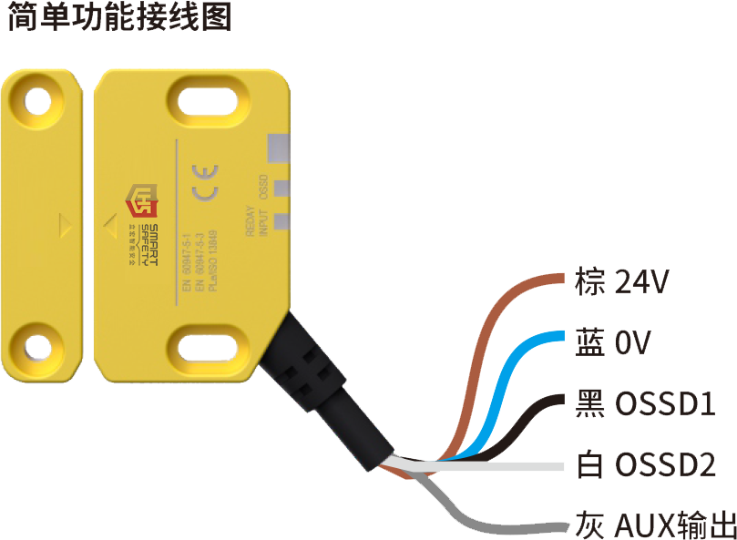 | Pin number | Signal definition | Color | Description |
1 | 24V | Brown | Positive power supply | |
2 | OSSD2 | White | safety output 2 | |
3 | 0V | Blue | Negative power supply | |
4 | OSSD1 | Black | safety output 1 | |
5 | AUX output | Gray | Auxiliary output 1 |
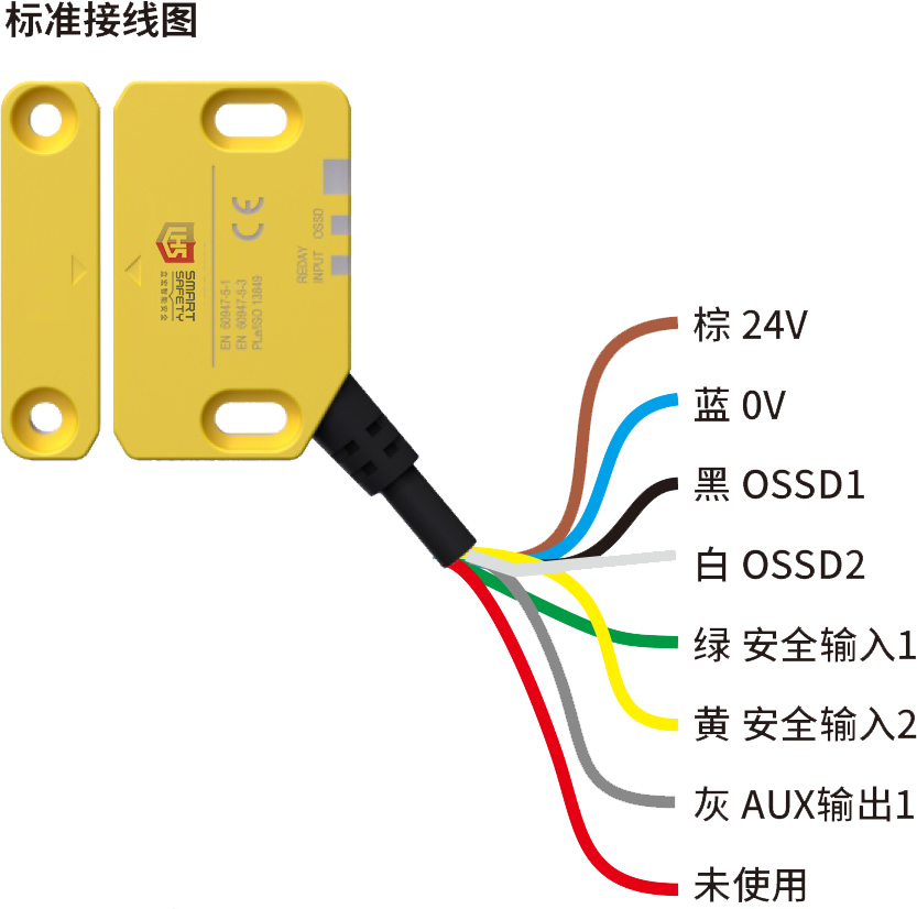 | Pin number | Signal definition | Color | Description |
1 | AUX output 1 | Gray | Auxiliary output 1 | |
2 | 24V | Brown | Positive power supply | |
3 | Not used | Red | Not used | |
4 | safety input 2 | Yellow | Cascade input 2 | |
5 | OSSD1 | Black | safety output 1 | |
6 | OSSD2 | White | safety output 2 | |
7 | 0V | Blue | Negative power supply | |
8 | safety input 1 | Green | Cascade input 1 |
| Pin number | Signal definition | Color | Description |
1 | 24V | Brown | Positive power supply | |
2 | Safety input 1 | Green | cascade input 1 | |
3 | 0V | Blue | Negative power supply | |
4 | OSSD1 | Black | Safety output 1 | |
5 | AUX output1 | Gray | Auxiliary output 1 | |
6 | Safety input 2 | Yellow | cascade input 2 | |
7 | OSSD2 | White | Safety output 2 | |
8 | Self-holding/EDM selection input | Pink | Self-holding/EDM selection input | |
9 | Not used | Red | Not used | |
10 | — | — | — | |
11 | Reset/EDM input | Purple | Reset/EDM input | |
12 | — | — | — |
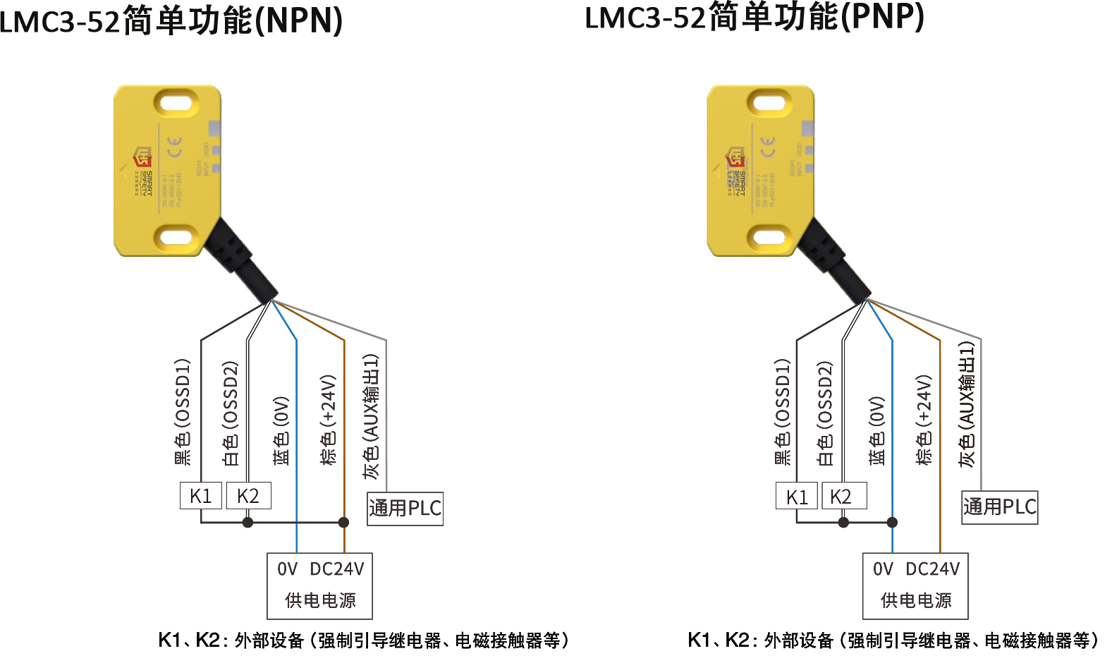 |  |  |
| Wiring example for cascade connection | High-functioning self-protection function: | |||
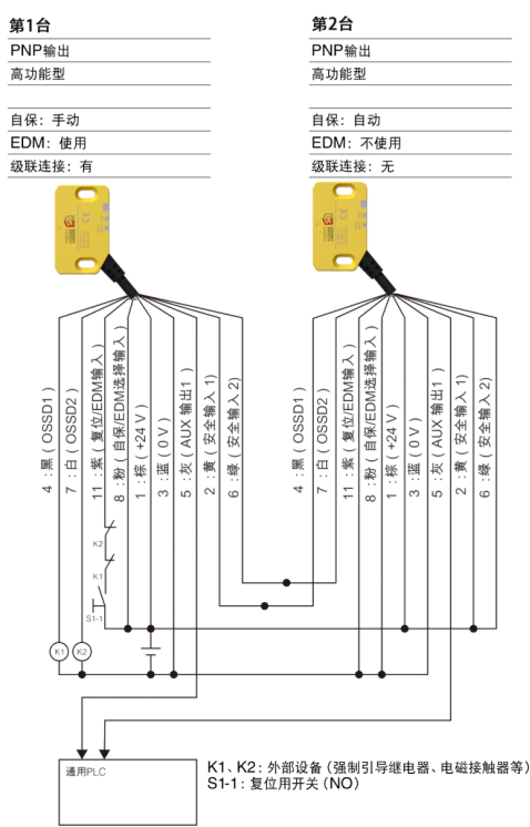 | The self-protection function is a feature that prevents the OSSD from automatically switching from OFF state to ON state. This function can prevent accidental startup or restart of the device. To restore from the state where the self-protection is active to the normal operating state, a reset operation is required. The basic function type and standard type can not set the self-protection function. The self-protection function is fixed to "Automatic" The self-protection function of high-function type can be selected from two types:"Automatic"and"Manual". "Automatic"and"Manual" here refer to following actions: | |||
Automatic: | ||||
When the OSSD meets the condition for switching to the ON state(for example, the door is in the closed state), it shall switch to the ON state immediately. | ||||
Manual: | ||||
Even if the OSSD meets the condition for switching to the ON state, it shall remain in the OFF state(self-holding state). | ||||
<Release of self-holding state> | ||||
To switch the OSSD to the ON state and start the equipment, a reset operation must be performed under the conditions that the door with GS(non-contact)installed is closed and the equipment is ready for startup.Through this,the OSSD will switch to the ON state,and the self-holding state can be released. | ||||
Setting of Self-holding function | ||||
Self-holding function | EDM function | Reset/EDM input(Purple) | Self-holding/EDM function selection input(Pink) | |
Automatic | Not in use | 0V | 0V | |
Automatic | in use | Connect to 24 V via NC contact of relay | Open | |
Manual | Not in use | Connect to 24 V via NO reset switch | Connect to 24 V | |
Manual | in use | Connect to 24V via NO reset switch and NC contact of relay | Connect to 24 V | |

Lihong Safety Equipment Engineering (Shanghai) Co., Ltd.
E-Mail: info@lh-safety.com
Address: 581 Xiuchuan Road, Chuansha Town, Pudong New District, Shanghai
(Greenland East Coast International Plaza-Room A 313)
Copyright ? Lihong Safety Equipment Engineering (Shanghai) Co., Ltd. ICP19034341-1 Technical Support: lanjujing